To find out more about the WCs
To find out more about the WCs
The principles of LW
Electrical structures are designed to transmit and distribute electrical power across the whole country. Their size depends on the specific dictates of electrical phenomena — such as the necessary separation between conductors of different phases. In particular, the electrical insulation of conductive elements is ensured by air distances and insulating materials: glass, porcelain, etc. The same principle applies to Live Working, with the additional constraint of an operator and tools that move in the air gap. So additional rules are needed to take these constraints into account and so ensure the safety of operators.
THE FRENCH LW METHOD
Unlike the most widespread approach, based on a corpus of detailed and predetermined operating procedures for each type of operation, the French method for LW leaves more to the workers' initiative. This is based on four principles:
rules assembled in the Working Conditions,
approved, periodically inspected tools,
specific training in LW delivered by approved training centres,
management involvement and surveillance.
The Working Conditions contain the rules that operators must follow to undertake live working. They allow the risks of short-circuit and electric shock to be controlled. There is one Working Conditions corpus for each voltage level. All the Working Conditions volumes are organised in the same way, and follow the sequence of an operation from feasibility to completion.
Like the Working Conditions, the technical data sheets are collected by voltage level. Each technical data sheet specifies the function of the tool, its electrical and/or mechanical characteristics, as well as its conditions of use, storage, maintenance and inspection.
In practice, before each job and whatever the voltage, the operation to be performed is prepared in the greatest detail. The preparer will analyse the risks, select the working method or methods to be used, identify the tools required and write the operating procedure. At the beginning of the work, the work foreman describes this process to all the operators, so that everyone knows their role.
The work foreman then ensures the operating procedure and sequence of working phases is followed. This approach allows both management of risks in advance, covered in the reference documents (Working Conditions and TDS), and management in situ during preparation of each job.
NO SHORT-CIRCUIT, NO ELECTRIC SHOCK
The Working Conditions define the general rules to be followed during live working. They come from a set of studies, physical calculations and experiments as well as a risks analysis based on two principles: controlling the insulation, controlling the energy and controlling the organisation, as well as preventing failures.
Firstly, it is advisable to ensure, at any time and for each level of voltage, support for the insulation of operators or conductive parts moving in the work area. If the insulation is breached between two points at different potentials (phase/earth or between phases), a short-circuit is created. If an operator is included in this circuit, this is an electric shock. Controlling the insulation involves defining minimum distances required between the operator and conductive elements and studying the conductivity of the tools. Furthermore, defining these distances means limiting overvoltage levels: operating overvoltages — by establishing a Special Operating Regime (SOR) — and overvoltages due to lightning — by prohibiting working during a storm.
Besides insulation, it is advisable to control the different energies on the network during an LW job, in order to protect the operator from the effects of an electric shock, such as from a surrounding accidental electrical arc. This is done by considering three forms of energy. Firstly, and obviously, active energy due to the current passing through the structure. Secondly, reactive energy, due to induction, if working on a live installation off-load or at floating potential. Finally, short-circuit energy, in the event of insulation failure.
In addition to defining these technical rules, organisation of the work is documented to ensure the safety of operators against electrical risks.
KEEP YOUR DISTANCE...
How are insulation breaches avoided? Firstly, just as when sizing structures, by exploiting the remarkable properties of the air around us. Available everywhere, free, with high dielectric properties, able to regenerate itself if ionised, air is the reference insulator. The basic principle for protecting the operator is therefore to continuously maintain an adequate air distance between him and objects (conductors, devices, structures) at potentials differing from his own. This safety distance, called the 'working distance', is the sum of a necessary insulation distance (d), called the voltage distance, and a working distance (g) taking account of inadvertent movements by the operator. Just imagine a wasp buzzing around the worker to understand the benefit of this additional precaution..., or working distance = t + g.
It required many years of study and research to establish the international reference (standard NF EN 61472) used as the basis for calculating the voltage distance. It takes account of the nominal voltage of the structure involved, the final peak overvoltage levels likely to appear on the network, as well as factors such as altitude, shape and dimensions of conductive objects inserted in the gap, etc.
For LV, the voltage distance is negligible (a few millimetres) and the working distance comes down to the ergonomic distance, about 30 cm.
For HV-A, a working distance is specified for each gap (phase/earth and phase/phase). To make it easier to calculate and to allow tools to be combined, SERECT has developed the concept of 'protective elements' (PE); one PE is equivalent to 10 centimetres of air. For example, for a phase/earth gap on a 20 kV voltage network, the working distance must be 0.60 m or 6 PE. The advantage of this new unit lies in the possibility of adding air distances, lengths of insulating tube and thicknesses of blankets, protectors or insulating gloves. The technical data sheets for tools specify the number of PE attributed to each insulating tool.
Finally, for HV-B, although the laws of physics stay the same, phenomena are accentuated. The concept of PE can no longer be used. Working distances defined are therefore air distances that take into account different overvoltage ranges, the volume of conductive parts handled in the gaps and the working method used.
PROTECTION APPROPRIATE TO EACH RISK
The Working Conditions define different PPE to be worn. These must fulfil three functions:
protect the operator from an electric shock under LV and HV-A ranges,
protect the operator from the effects of a possible high power electrical arc, for all voltage ranges,
protect the operator from the effects of the intense electric field under HV-B.
For LV and HV-A, protection against electric shock is provided particularly by using insulating gloves during insulating glove working.
For HV-A, protection against step voltage risks is provided by special shoes or boots.
A high power electrical arc produces heat and light emissions, a sound wave and, in some cases, flying particles. To protect himself from these effects, the operator wears a visor (protection against heat emissions and flying particles), safety glasses (against light emissions) and ear defenders (for HV-B only, against the sound wave).
The operator is protected from the electric field, strong for HV-B, by conductive clothing acting as a Faraday cage during bare-hand working. So we have the famous yellow outfit – the first generations were white then blue-grey – made from a composite material comprising a non-flammable and thermally-insulating polymer fibre and a conductive metal fibre.
As the 'cage' has to be closed, the outfit also includes boots, gloves and a hood with visor (this deflects the field lines away from the face, inevitably uncovered).
THREE WORKING METHODS
There are three methods of live working: hot stick working, bare hand working and insulating glove working. The difference lies in the position of the operator relative to the potential on which he wishes to work.
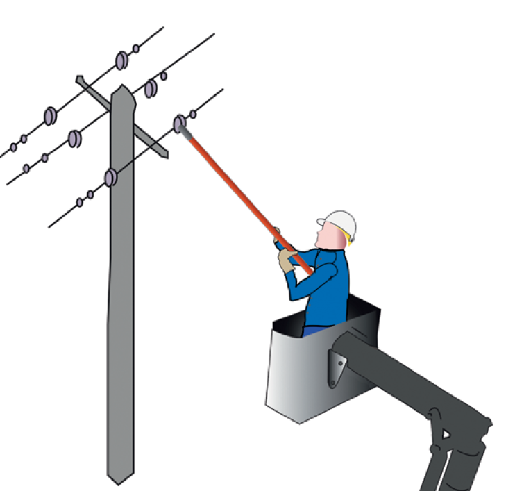
Hot stick method
In the hand stick working method, the first developed, the operator remains at earth potential. In order not to come into contact with exposed live parts, he works using insulating tools fixed to the end of sticks or insulating ropes. Used in all voltage ranges, this method requires low investment but is ergonomically limited, particularly when the distances to be used become large. For HV-A, a metal-armed lifting platform can be used. For HV-B, work is generally done from the tower for work on lines and from the ground for work in substations.
Bare hand method
In the bare hand working method, the operator is insulated from the earth and is brought to the potential of the element he is working on. He is therefore in a similar position to a bird sitting on an electric line. At all times he must remain at the working distance from all elements in his environment that are at a different potential to the element he is working on. This applies to him and to the tools or conductive parts he handles. Used for HV-A and HV-B voltage ranges, this method is very comfortable because it is ergonomically easy to work. The work is done from a platform insulating the operator from earth potential. For HV-A, an insulating-arm lifting platform can be used. For HV-B, a Substation LW MEWP and an IPT (Insulating Positioning Tower) can be used for work in substations, and a hoist ladder, beam ladder or LW chair for working on lines.
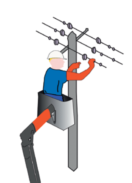
Rubber glove method
In the insulating glove working method, the operator is protected depending on the voltage range of the parts he is working on and enters the area located between live exposed parts and the safety distance. Used for LV and HV-A, this method cannot be used for HV-B because of the large distances required. For HV-A, the operator uses insulating gloves and works from an insulated arm platform. More ergonomic than safe clearance working, insulating glove working on HV-A also allows easier movement close to the supports (poles).